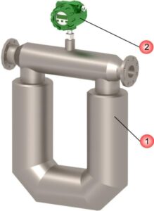
A unique type of flow meter, the Coriolis mass flowmeter, is comprised of several distinctive components.

One option for installation of the Transmitter is to mount it directly on the flow sensor, which is the standard integral version. Alternatively, the Transmitter can be installed remotely, which is the optional remote version.
The innovative sensor design features a measuring chamber complete with inlet and outlet flanges, making it ideal for easy pipeline mounting. Within the measuring chamber are two parallel U-shaped flow tubes, which are set in vibration using an electromagnetic coil and magnet.
The functionality of this system operates on the principle of the Coriolis effect.
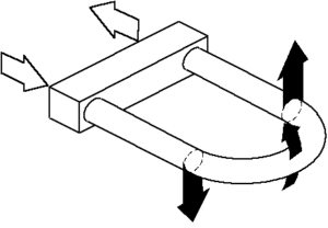
Figure 2.1 illustrates the dynamic forces impacting the flow tube as liquid passes through it during the half-cycle fluctuations when the tube moves upwards.
As fluid flows through the tube, it generates a resistance to motion caused by inertial forces. These forces result from the fluid’s upward motion and downward pressure on the tube. The momentum in the vertical direction is quantified by observing the bending of the tube. When the liquid exits the pipe, it creates inertial forces that push the tube upwards, causing it to twist. During the second half of the oscillation cycle, as the tube moves downwards, it twists in the opposite direction. This phenomenon is referred to as the Coriolis effect and is responsible for the tube’s twisting motion.

The performance of a Coriolis mass flow meter depends on the twist angle of the sensor tube, which is directly related to the volume of fluid passing through the tube in a given time. The meter features electromagnetic detectors located on both the inlet and outlet sides of the tube, which measure the frequency of tube oscillation. By measuring the time delay between signals from these detectors, the rate of flow can be determined.
The rate of flow, denoted by Q, is proportional to the phase angle difference between the left and right detector signals, which is determined by the time delay Δt. When there is no flow, the tubes do not twist, and there is no time delay between the signals from the left and right detectors. As the flow rate increases, the twist angle of the tube increases, leading to a larger time delay between the detector signals and a higher phase angle difference.
In summary, the Coriolis mass flow meter utilizes the Coriolis effect to measure fluid flow rate by analyzing the twist angle of a sensor tube and the time delay between signals from electromagnetic detectors. The higher the flow rate, the greater the twist angle and time delay, leading to a larger phase angle difference and a higher measured flow rate.
Q = K * Δt / 3.6 , kg/h (1.0)
where K – calibration coefficient, g/s/µs determined using pure water;
Δt – time delay between the detectors signals, µs.
The determination of a medium’s density is achieved by measuring the oscillation period of the flow tubes. This period is directly proportional to the medium’s density. To ensure accuracy, the density measuring channel is calibrated using two different fluid mediums with precisely known densities, such as water and air. For each medium, the coriolis controller records the corresponding flow tube oscillation period. This data is then displayed on the menu item 70.
The medium density and its corresponding oscillation period for both water and air are entered into the menu display, specifically menu items 62 to 65, or through Modbus. With the linear relationship between the oscillation period and density, the coriolis flow meter can accurately determine the actual medium density using the measured oscillation period. This method ensures precise density measurements of various fluid mediums.
A specialized type of temperature sensor, known as a Pt 100 sensor made from platinum, is utilized for precise temperature measurements. The temperature readings captured by this sensor are employed to make necessary adjustments to the flow and density of the medium when the temperature changes. At the time of manufacture, the temperature correction factors for both flow and density are entered into the coriolis flow meter memory. These values can be modified through the device’s menu display or Modbus interface as needed.
Gas flow measurements with Coriolis flow meters can be affected by changes in medium pressure, requiring manual correction to ensure accurate readings. By enabling the manual correction mode in the meter’s menu, users can enter the actual pressure value obtained from an external pressure sensor, which will then be used to adjust the flow readings accordingly. This ensures that the flow measurements remain accurate and reliable, even when the medium pressure changes.
The innovative sensor technology captures and processes the time delay between signals from the detectors to generate a distinctive electrical signal. This primary signal is then transmitted to an electronic transmitter, which can be located either directly on the sensor or remotely. The transmitter boasts a powerful digital signal processor, which is capable of performing advanced calculations, such as mass and volume flow values, temperature correction, and output signal generation. Additionally, the transmitter is equipped with a high-tech display that showcases the collected data from the coriolis flow controller. Furthermore, it can drive analog outputs and transmit the processed data to digital communication protocols, such as HART or ModBus registers, thus offering seamless integration into modern systems.
Features of the coriolis gas flow meter measurement principle: