Call us at 775-419-3476. No need to select a department, dial an extension or tell a machine why you’re calling. Call us, and we’ll help you. It’s that easy.

User Manual

User Video Instructions


Mass Flow Meters and Controllers Re-imagined

CONGRATULATIONS! You just got your meter and you want to hook it up! We have installed TWO wires, a RED wire that hooks up to the + side of 24 VDC and the WHITE wire that hooks up to the GROUND side of your 24 VDC power supply with at least 200 mA capability.
Please connect it to your power supply and see how the meter works and download the Configuration Software and follow the instructions to connect to your meter with either the USB, BlueTooth, or ModBus RTU.
When done remove those two short wires and keep handy for other quick tests.
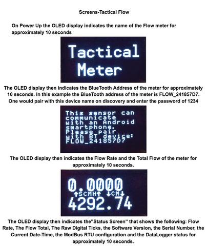
Most folks want to get moving quickly so they opt to use the BlueTooth because no wiring is required. Remember, as shown below, that you FIRST tell your PC that you have a BlueTooth located nearby and PAIR it with the Pairing Code of 1234. Windows may enumerate TWO COM ports, it is normally the FIRST one it chooses.
Get your two page Wiring Diagram below, download here
The links and videos below are available from the user program and they automatically serve the content that is related to the function that is being used on the screen the user is using. There is no need to review these videos unless you have a desire to see how the meter works without actually having to use one. Consider these videos as a video guided tour of the Thermal Mass Flow Meter. These videos are fully responsive so you may view them on a Smart Phone.


Main User Program Index

Main User Instructions

We demonstrate the operation of the User Program with a Windows Machine to allow you to understand the basic principles of the mass flow meter/controller. We demonstrate the operation of the User Program with a Windows Machine to allow you to understand the basic principles of the mass flow meter/controller. This video show all aspects of the program and is available in each category from the index values shown above.

Bluetooth Instructions

We demonstrate the method of setting up the mass flow meter/controller with a Windows Machine with Bluetooth using the User Program.
The Pairing Code is 1234 on all the flow meters.

MORE Bluetooth Instructions

We demonstrate more methods for using the PC and Bluetooth and how to discover which Bluetooth device is connected to your Flow Meter.

Flowmeter Validation Instructions

We demonstrate the method of validating the calibration of the mass flow meter/controller with a Windows Machine with the User Program.

Datalog Instructions

We demonstrate the method of downloading/viewing and plotting the datalog data from the mass flow meter/controller with a Windows Machine with the User Program.

Voltage Output Instructions

This video shows how the 4-20 and 0-5 VDC Outputs can be validated manually.

Adjusting the 0-5 and 4-20 outputs

This video shows examples of adjusting the 4-20 and 0-5 VDC outputs to correlate with the attached data acquisition system.

Voltage and Current Output Instructions

We demonstrate the method of validating the calibration of the mass flow meter/controller with a Windows Machine with the User Program.

Terminal and ModBus Instructions

We demonstrate the method of using the Terminal and the ModBus functions for the mass flow meter/controller with a Windows Machine with the User Program.

Totalizer and Pulse Counter Instructions

We demonstrate the method of accessing the totalizer and pulse output of the mass flow meter/controller for a Windows Machine with the User Program.

Totalizer and Pulse Counter Configuration Instructions

We demonstrate the method of setting up your Pulse Counter to count at the rate that is supported by your connected pulse counter. We show the part that accomplishes the pulse counting as well as the specification sheet for an Omron H7EC as an example.

Setup Instructions

We demonstrate the setup screen of the mass flow meter/controller for a Windows Machine with the User Program.

Configuration Instructions

We demonstrate the method of accessing the configuration of the mass flow meter/controller for a Windows Machine with the User Program.

Calibration Instructions

We demonstrate the method of accessing the calibration features of the mass flow meter/controller for a Windows Machine with the User Program.

The table below shows the Register addresses that are in place to support the use the same register scheme used in any Sage Metering ModBus equipped Thermal Mass Flow Meter. The Sage Metering product indicates the raw flow reading in mW, typically in the range of 40 mW to 900 mW. As such, we scale the output of the Mag Flow meter’s 0-32767 Raw Ticks output to the range of 40 to 900 mW when using the ModBus command 582. This provides for easy comparison of the raw values.

Refer to the screen samples below to understand what each of the screens means and indicates to the user.

The QR Code is VERY HANDY to read with your Smart Phone so you can have these instructions on your portable device when you go to the flow meter in the field. These videos render very fast on all Smart Phones.

© 2021, Mag Flow Meter

Request A Quote