Call us at 775-419-3476. No need to select a department, dial an extension or tell a machine why you’re calling. Call us, and we’ll help you. It’s that easy.


$2,112.00 – $10,450.00
MAG Flow Meters at the prices of High-End Clamp On Ultrasonic Flow Meters and feature accuracies of 0.5% of READING.
Amazing Sensitivity for conductivity requiring a minimum of 5 micro Siemens/cm (compared to more than 20 micro Siemens/cm required for competitors)… READ MORE
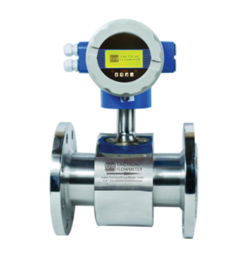
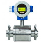
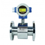
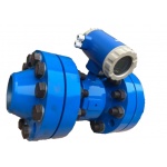
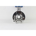
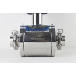
Electromagnetic flow meters, (aka mag meters or magnetic meters), are volumetric flow meters which do not have any moving parts. This lack of moving parts reduces the need for maintenance or replacement. Our mag flow meters have an accuracy over a wide flow range that can often exceed ± 0.5% of flow rate.Our MAG flow meters are ideal for liquids. They ship from stock and are configured for you. In-stock and at prices that beats our competition.
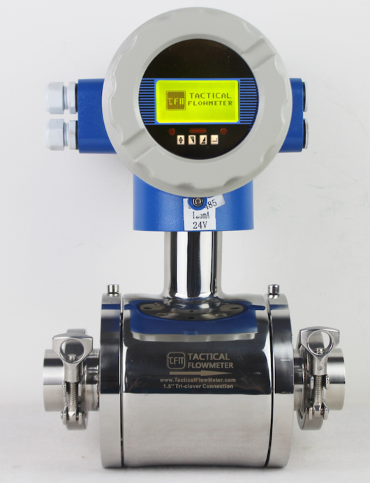
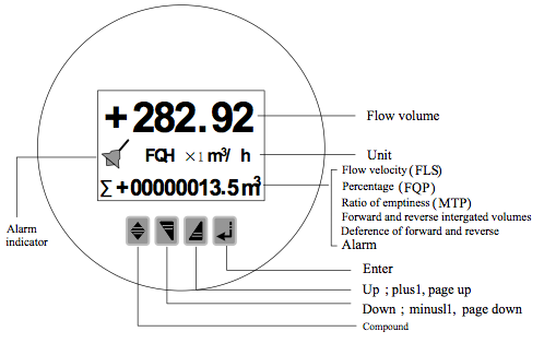
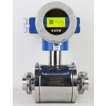
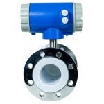
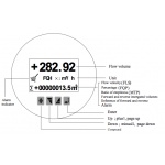
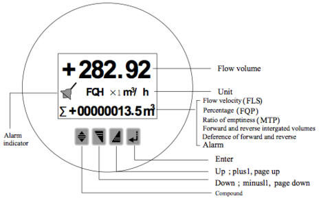 Features LARGE LCD display, shows the Instantaneous Flow Rate, Total Flow, in user selectable units.
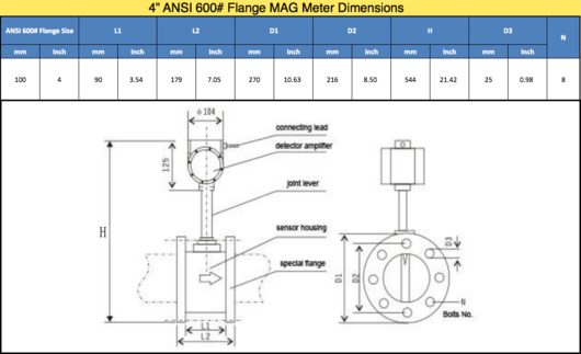
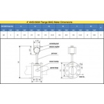
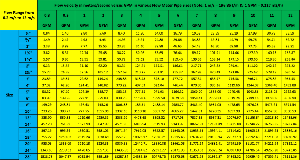
 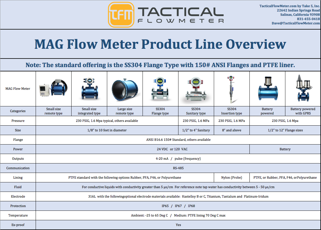 The table below gives a guideline of the nominal maximum GPM for various pipe sizes. Flows in well designed piping systems, to minimize wear and noise, and energy, are typically no more than 10 m/s max. Note these meters can easily go to 12 m/s for systems, such as high pressure fire fighting systems and blowdown systems.
 Simulating and validating the 4-20 mA output using the User Interface with 03210 is detailed below. You may ALTER these values (AnalogZero and AnlgRange) using 03210 and they will revert when you exit.
Note the 4-20 mA output for this meter is POWERED by the meter. DO NOT connect to a PLC that provides 24 VDC. Connection is made to the 4-20 mA signal using a reading mode just like a Fluke Meter configured to read 4-20 mA DC. The MAG meter provides the 24 VDC for outputting the value to the INPUT of your PLC. Every PLC has the ability to be configured to read this type of 4-20 mA output. (Note: From the main menu the AnalogZero is 49 hits of the UP arrow.) (ADJUSTMENT of the 4-20 Output drive is attained using secret password of 19818 and is risky to use.)
If the meter indicates a NEGATIVE flow you may REVERSE the flow using Menu 8: Flow Direction and change it from the indicated value to either the REVERSE or FORWARD value.
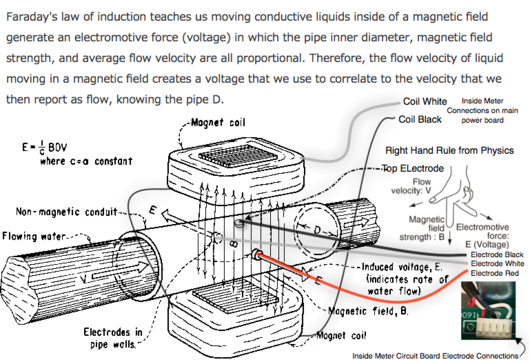
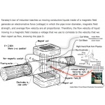
Note: If the flow indicates a NEGATIVE FLOW number AND you know it is going from LEFT to RIGHT Menu 8 may be used to FLIP the sign. The Flow Direct is a "switch" to take care of the "Right Hand Rule" with regards to the direction of the current vector in Faraday's Law and does not require the direction to agree with the arrow on the meter.
If the meter indicates a NEGATIVE flow on the display and does not output 4-20 mA it means that Menu 13: SigmaN Ena can be set to ENABLE to allow the 4-20 to indicate flow in both the + and negative direction. Set Menu 13: SigmaN Ena to DISABLE if you do not want flow to indicate if the flow reverses. In this case the mA will go to 0 mA to indicate reverse flow, but not the magnitude in rate. However, the NEGATIVE Totalizer will account for the negative flow.
IMPORTANT NOTE: This meter is not a "Loop Powered" device, unlike almost all temperature and pressure transducers that are loop powered. This meter takes 500 mA to run so you can see that they can not be Loop Powered. It is CRITICAL that 24 VDC is NOT connected to the 4-20 mA signal lines of COM and I+ where COM is connected to the "low" side,-, of the 4-20 mA and the I+ is connected to the "high" side,+. Your PLC has a mode in it to read these meters that does NOT involve sending power to the meter. These meters are SOURCING the 24 VDC. Connecting 24 VDC to the Current Output lines may void warranty.
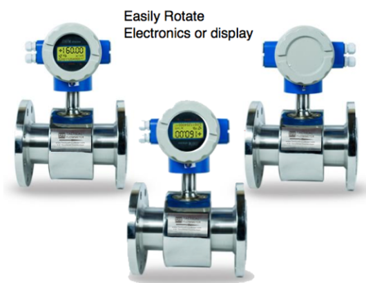
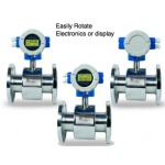
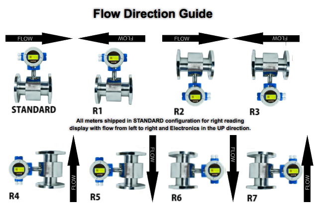
Note: The following display orientations can be ordered so the user does not have to orient in the field.
Simulating and validating the 4-20 mA output using the User Interface with 03210 is detailed below. You may ALTER these values (AnalogZero and AnlgRange) using 03210 and they will revert when you exit.
Note the 4-20 mA output for this meter is POWERED by the meter. DO NOT connect to a PLC that provides 24 VDC. Connection is made to the 4-20 mA signal using a reading mode just like a Fluke Meter configured to read 4-20 mA DC. The MAG meter provides the 24 VDC for outputting the value to the INPUT of your PLC. Every PLC has the ability to be configured to read this type of 4-20 mA output. (Note: From the main menu the AnalogZero is 49 hits of the UP arrow.) (ADJUSTMENT of the 4-20 Output drive is attained using secret password of 19818 and is risky to use.)
If the meter indicates a NEGATIVE flow you may REVERSE the flow using Menu 8: Flow Direction and change it from the indicated value to either the REVERSE or FORWARD value.
Note: If the flow indicates a NEGATIVE FLOW number AND you know it is going from LEFT to RIGHT Menu 8 may be used to FLIP the sign. The Flow Direct is a "switch" to take care of the "Right Hand Rule" with regards to the direction of the current vector in Faraday's Law and does not require the direction to agree with the arrow on the meter.
If the meter indicates a NEGATIVE flow on the display and does not output 4-20 mA it means that Menu 13: SigmaN Ena can be set to ENABLE to allow the 4-20 to indicate flow in both the + and negative direction. Set Menu 13: SigmaN Ena to DISABLE if you do not want flow to indicate if the flow reverses. In this case the mA will go to 0 mA to indicate reverse flow, but not the magnitude in rate. However, the NEGATIVE Totalizer will account for the negative flow.
IMPORTANT NOTE: This meter is not a "Loop Powered" device, unlike almost all temperature and pressure transducers that are loop powered. This meter takes 500 mA to run so you can see that they can not be Loop Powered. It is CRITICAL that 24 VDC is NOT connected to the 4-20 mA signal lines of COM and I+ where COM is connected to the "low" side,-, of the 4-20 mA and the I+ is connected to the "high" side,+. Your PLC has a mode in it to read these meters that does NOT involve sending power to the meter. These meters are SOURCING the 24 VDC. Connecting 24 VDC to the Current Output lines may void warranty.
Note: The following display orientations can be ordered so the user does not have to orient in the field.
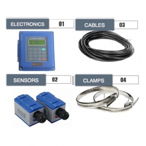
Ultrasonic Liquid Flow Meter with Thermal Energy/BTU Capability
Ultrasonic flowmeters use sound waves to determine the velocity of a fluid flowing in a pipe $2,400.00 – $2,475.00Ultrasonic flowmeters use sound waves to determine the velocity of a fluid flowing in a pipe. At no flow conditions, the frequencies of an ultrasonic wave transmitted into a pipe & its reflections from the fluid are the same.
> view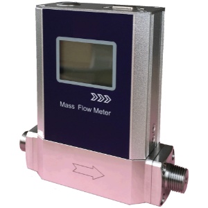
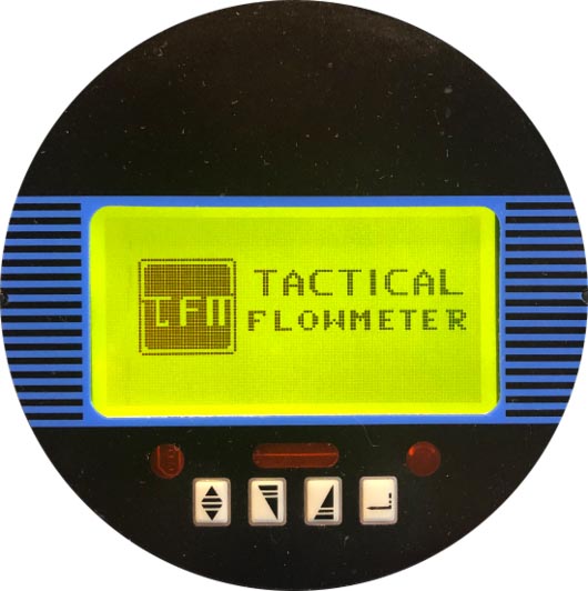
100 SCCM to 100 SLPM Low Flow Tactical Flow Meter, Battery Powered for 2 years
Low Flow Gas Mass flow meters for methane $800.00Find your medical gas flow meter easily amongst the 209 products from the ... Oxygen or Air 0 – 15 L/min st&ard flow rate Low flow, 0 – 3.5 & 0 – 5 ... PRODUCT DETAILS The TSI Mass Flow Meter 41401 (0.01-20 L/min / Air ... a centralized medical gas pipeline system, to the patient with the use of a mask or a cannula.
> view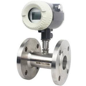
Turbine Flow Meter
Designed for for liquids, diesel, and oil $1,230.00A turbine flow meter is used for volumetric total flow &/or flow rate measurement & has a relatively simple working principle. As fluid flows through the turbine meter, it impinges upon turbine blades that are free to rotate about an axis along the center line of the turbine housing. The angular (rotational) velocity of the turbine rotor is directly proportional to th
> view


