Call us at 775-419-3476. No need to select a department, dial an extension or tell a machine why you’re calling. Call us, and we’ll help you. It’s that easy.
Electrical connections should be performed in the following sequence (see Figure 2.11):
Tighten the cover of the transmitter.
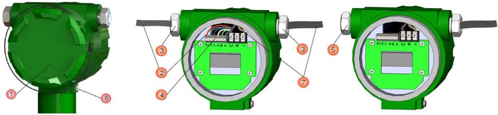
Figure 2.11 – Electrical connections
Table 2.5 – Notes for Figure 2.11
| Item №. | Description |
| 1 | Back cover of the transmitter |
| 2 | Signal cable |
| 3 | Cable entries |
| 4 | Wiring Terminal block |
| 5 | Blind plug |
| 6 | Ground terminal |
| 7 | Power cable |
Maximum length of the power cable is 1000 ft (300 m) with minimum wire section 0.8 mm2 (AWG18).
The current and pulse outputs should use a twisted pair wire with a maximum length of 150 m and minimal wire section 0.5 mm2 (AWG20).
Remote transmitters are connected through a special 9-conductor shielded cable with maximum length of 1000 ft (300 m.) The connection diagram is shown in Figure C.1 of Appendix . After mounting and electrical connection the zero point adjustment should be performed (see paragraph 2.5.4 “Zero point adjustment”).
| CAUTION! |
| When using the coriolis mass flow controller in hazardous areas, apply the requirements for explosion protction provided in paragraph 2.4.2 “Installation with explosion protection” |