Call us at 775-419-3476. No need to select a department, dial an extension or tell a machine why you’re calling. Call us, and we’ll help you. It’s that easy.
The coriolis mass flowmeter consists of the following units
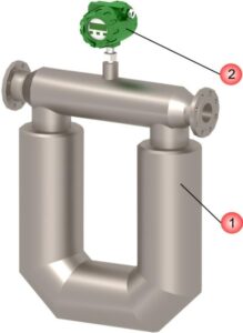
The Transmitter may be mounted directly on the flow sensor (integral version, standard) or remotely (remote version, optional).
The sensor is comprised of a measuring chamber with inlet and outlet flanges for mounting on a pipeline. Inside the measuring chamber there are two parallel U-shaped flow tubes, which vibrate by means of an electromagnetic coil and a magnet.
The principle of operation is based on the Coriolis effect.
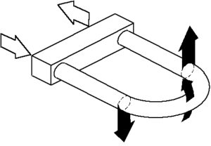
Figure 1.2 shows the forces affecting the flow tube through which the measured liquid is flowing, during the half-cycle fluctuations, when the tube moves up.
The liquid flowing into the tube creates a resistance to movement due to inertial forces, or the fluid upward movement and downward pressure on the tube by inertial forces. The vertical momentum is measured by driving the tube bend, the liquid, flowing out of the pipe, (inertial forces) pushes the tube up. This causes the tube to twist. When the tube is moving down in the second half of the oscillation cycle, it twists in the opposite direction. This twisting is called Coriolis effect.
Twist angle of the sensor tube is directly proportional to the amount of fluid passing through the tube within the specific time. Electromagnetic detectors situated on both inlet (left) and outlet (right) side of the tube, measure the tube oscillation frequency. Coriolis mass flow meter rate is determined by measuring the time delay between the signals of those detectors. This is a phase angle measurement. When there is no flow, the tubes don’t twist and there is no time delay between, or phase angle difference, the left and right detector signals. Coriolis mass flow meter rate Q is proportional to the time delay Δt between the detector signals.
Q = K * Δt / 3.6 , kg/h (1.0)
where K – calibration coefficient, g/s/µs determined using pure water;
Δt – time delay between the detectors signals, µs.
The density of the medium is determined by measuring the period of oscillation of the flow tubes, which is proportional to the density of the medium. The density measuring channel is calibrated for two different fluid mediums with exactly known (measured by standard density meter) density (water and air). For each medium the coriolis controller measures the flow tube oscillation period corresponding to the medium density. The measured value of the oscillation period is shown in Menu item 70 (see the display menu). The medium density and the corresponding oscillation period for both water and air are entered in the menu display (Menu items 62 … 65) or through Modbus. Due to the linear dependency of the oscillation period of the density the actual medium density can be determined by the oscillation period measured by the coriolis flow meter.
Temperature measurement is performed using a platinum, Pt 100, temperature sensor. The measured temperature is used for correction of the flow and density when the medium temperature changes. Temperature correction factors of flow and density are entered in the coriolis flow meter memory at the factory and can be changed through the menu display or Modbus.
Coriolis gas flow meters require manual correction of flow when the medium pressure changes. When manual correction mode is enabled in the menu, the user will specify the actual pressure value taken from the external pressure sensor.
The sensor generates the primary electrical signal containing information of the time delay between the signals of the detectors. The primary signal is transmitted to the electronic transmitter located directly on the sensor or remotely from it. The transmitter uses a digital signal processor to processes the primary signal, calculates mass and volume flow values, temperature correction, generates output signals, and displays the information on the coriolis flow controller’s display, drives the analog outputs and supplies the data to the ModBus registers or other digital communication protocols, such as HART.
Features of the coriolis gas flow meter measurement principle: