Call us at 775-419-3476. No need to select a department, dial an extension or tell a machine why you’re calling. Call us, and we’ll help you. It’s that easy.
The Coriolis gas flow meter complies with Underwriters Laboratories Inc. for telemetering equipment for use in Hazardous locations
Class I, Groups C and D; Class II, Groups E, F and G; Class I, Groups A, B, C and D, Division 2.
Intrinsically safe mass flow sensors, for use in Class I, Groups C and D; Class II, Groups E, F and G hazardous locations and also suitable for Class I, Groups A, B,
C and D, Division 2 hazardous locations
Optional Booster Amplifier for use in Class I, Division 1, Groups C and D; Class I, Division 2, Groups A, B, C and D; Class II,
Division 1, Groups E, F and G, Hazardous Locations Providing Intrinsically Safe Circuits
As well, the transmitter , sensor and booster amplifier complied with GOST R 51330.1, and the input and output “intrinsically safe” level «ib» complied with GOST R 51330.10.
The Coriolis mass flow controllers with the explosion-proof option “TFM-TFM 1001-Ex» have the integral type of protection “flameproof enclosure” complies with GOST R 51330.1, and the input and output “intrinsically safe” level «ib» complies with GOST R 51330.10. The sensor explosion proof grade is shown below in Table 1.7.
Table 1.7 – Sensor explosion proof grade
| Temperature code | Explosion proof grade |
| “100” | 1Ex ibIICT4X |
| “200” | 1Ex ibIICT3X |
| “350” | 1Ex ibIICT1X |
Transmitter explosion proof grade is 1ExdibIICT6X.
The explosion proof grade is written on the name plates attached to the body of the sensor of a meter with the explosion-proof modification and to the transmitter.
The name plate must remain affixed, and not altered on the coriolis gas flow meter ordered.
The “Х” letter in the explosion proof grade indicates the following special requirements:
– the measured medium temperature must not exceed the maximum temperature according to the explosion proof grade temperature group;
– explosion protection is provided under pressure not exceeding the maximum allowable pressure for the given modification;
– connection of external circuits to the coriolis mass flow meter must be implemented through the cable entries compliant with GOST R 51330.1;
– unused cable entries must be closed with the end cap supplied by the coriolis mass flow meter’s manufacturer or other end cap compliant with GOST R 51330.1;
– connection of the external devices to the pulse, current and digital outputs of the coriolis mass flowmeters of “Ex” modification must be implemented in accordance with GOST R 51330.1.
Explosion protection type of “flameproof enclosure” is implemented by putting the electrical parts of the coriolis mass flow meter into a flameproof enclosure in accordance with GOST R 51330.1, that prevents the explosion from exiting out of the coriolis mass flow meter into the explosive environment.
Explosion protection of the enclosure is ensured by the following means:
– the housing case can withstand an explosion test at the test pressure of 4 times the pressure of the explosion;
– axial thread length and number of full turns of the thread engagement must comply with GOST R 51330.1 requirements;
– the gaps and lengths of flat and cylindrical flameproof joints must comply with
GOST R 51330.1 requirements;
– maximum coriolis flow meter’s surface temperature in working conditions must not exceed the temperature range in accordance to GOST R 51330.0 for the temperature groups:
– Т4 for the coriolis flow controllers with temperature modification code «100»;
– Т3 for the coriolis flow controllers with temperature modification code «200»;
– Т1 for the coriolis mass flow meters with temperature modification code «350».
Explosion protection type of input and output “intrinsically safe” circuit level «ib» is ensured by the following means:
– external power supply and connection of the external devices to the pulse, current and digital outputs of the coriolis mass flow controllers of “Ex” modification must be implemented in accordance with GOST R 51330.1;
– the values of parameters of the left/right signal coils, drive coil and the temperature sensor circuits do not exceed the limits in accordance with GOST R 51330.10;
– spark safety barrier with Zener diodes must be applied by user;
– electrical clearances and creepage distances comply with GOST R 51330.10. Insulation resistance between the sensor outer shell and electrical circuits elements can withstand a testing voltage of 500 VAC rms;
– internal capacity and inductance of the circuit do not accumulate energy, dangerous for spark ignition gas mixtures of category IIC;
– current-conducting elements and electronic components of the coriolis mass flow meter circuit are protected from the environment influence with the shell, which provides the protection degree IP 65 according to GOST 14254.
– Block diagram of the coriolis mass flow meter is shown in Figure 1.3.
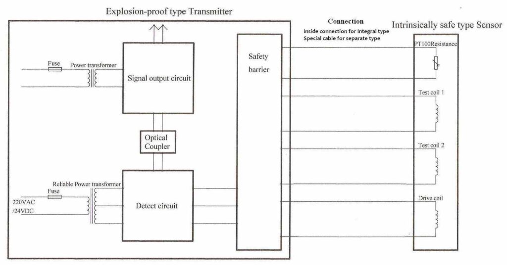
Figure 1.3 – Block diagram of the coriolis flow controller
The transmitterl, sensor and booster amplifier complied with GB3836.1-2010GB3836.2-2010 and GB3864-2010. it can be used in hazardous location Zone 1 and Zone 2. The range of ambient temperature of the product is -20 ℃- +40℃. The marking of the quipment is EX d [ib] IIB+H2 T6 Gb.
Input and output parameters of intrinsically safe circuits are shown in Tables 1.8 and 1.9.
| Parameter name | Parameter value | ||
| Left / right signal coils | Drive coil | Temperature sensor | |
| Maximum input voltage Ui, V | 5.4 | 10.5 | 5.4 |
| Maximum input current Ii, mA | 72 | 70 | 72 |
| Maximum input capacity Ci, pF | 50 | 50 | 50 |
| Maximum input inductance Li, mH | 2.2 | 3.5 | 0.010 |
| Maximum input power Pi, W | 0.097 | 0.184 | 0.097 |
| Parameter name | Parameter value for the circuit of | ||
| Left / right coil power | Drive coil power | Temperature sensor power | |
| Maximum output voltage Uo, V | 5.4 | 10.5 | 5.4 |
| Maximum output current Io, mA | 72 | 70 | 72 |
| Maximum output capacity Co, µF | 10 | 1 | 10 |
| Maximum output inductance Lo, mH | 5 | 4.5 | 5 |
| Maximum output power Po, W | 0.097 | 0.184 | 0.097 |
Parameters of the sensor coil windings are shown in Table 1.10.
Table 1.10 – Coil windings parameters
| Coil | Wire diameter, mm | Number of turns | Resistance, Ohm |
| Left / right signal coils | 0.13 | 500 | 20 ± 0.5 |
| Drive coil (DN10 – DN40) | 0.13 | 300 | 11 ± 0.5 |
| Drive coil (DN50 – DN200) | 0.27 | 300 | 8 ± 0.5 |
Maximum length of the connection cable for the separate type coriolis gas flow meter is 300 m.
Drive coil power circuits are electrically isolated from other circuits by means of the undamaged transformer according to GOST R 51330.10. Insulation between primary and secondary windings can withstand voltage of at least 1.5 kV.
Ambient temperature for the coriolis gas flow meters of “Ex” modification must be between -20 and +40 ºC.