Call us at 775-419-3476. No need to select a department, dial an extension or tell a machine why you’re calling. Call us, and we’ll help you. It’s that easy.
Prior to installation, it is necessary:
To install the coriolis mass flow controller in the pipeline do the following steps (see Figure 2.5):
When installing the coriolis flow controller any bending or torsional load on the joints should be avoided. Mating flange misalignment should be avoided.
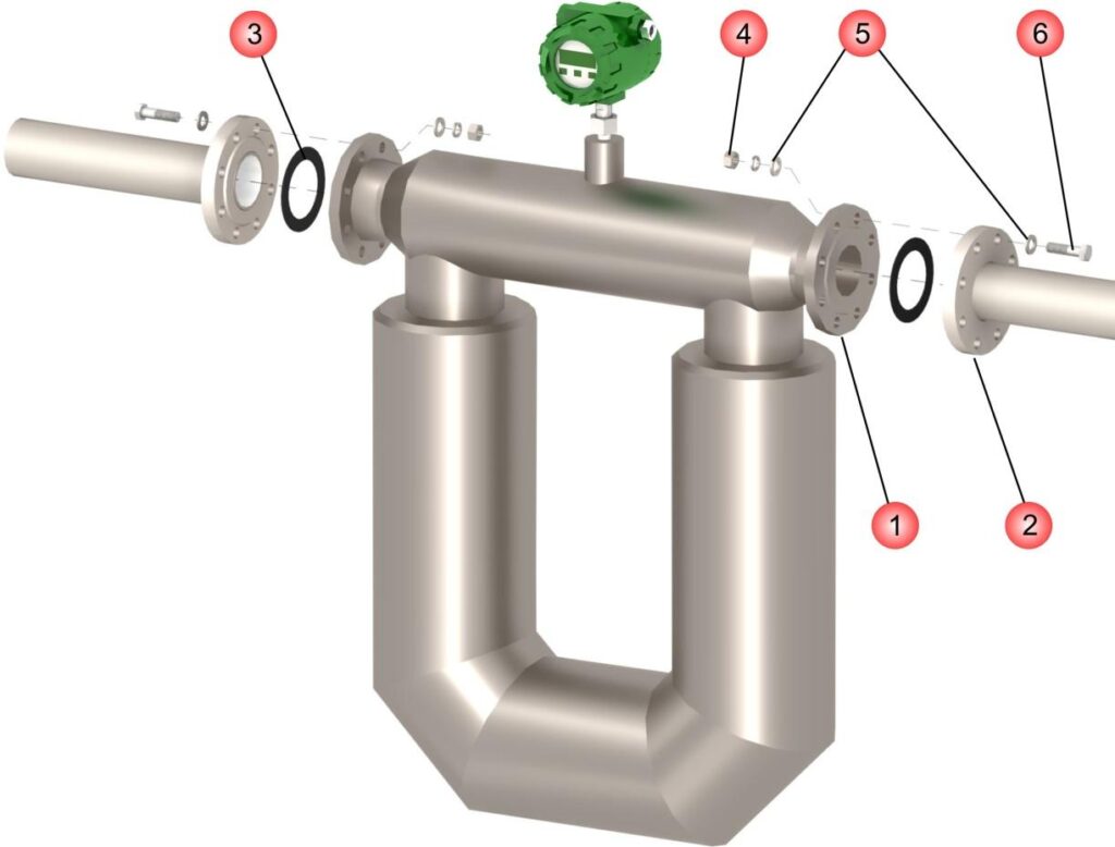
Figure 2.5 Installation of the coriolis flow controller in the pipeline
Table 2.3 – Notes for Figure 2.5
| Item No | Mounting part |
| 1 | flanges |
| 2 | Connection kit flanges |
| 3 | Gaskets |
| 4 | Nuts |
| 5 | Washers |
| 6 | Bolts (or stud bolts) |
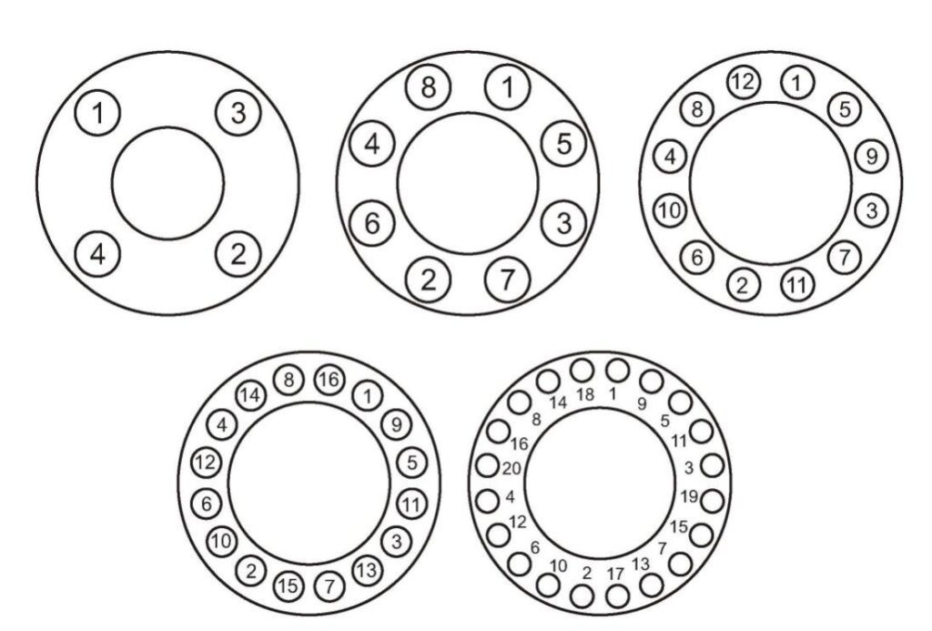
Figure 2.6 – The sequence of tightening the flange bolts
Transmitter of the separate type of the coriolis flow controller can be mounted as shown in Figure 2.7. Transmitter can be mounted with brackets or clamps to the rack, pipe or wall.
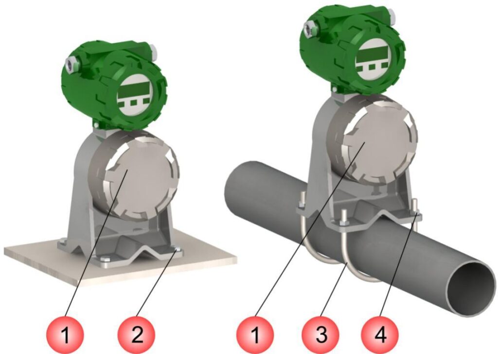
Figure 2.7 – Installation of remote transmitter type illustration
Table 2.4 – Notes for Figure 2.7
| Item # | Mounting part |
| 1 | Transmitter base |
| 2 | Bolts |
| 3 | Clamp |
| 4 | Nuts |
| CAUTION! |
| Do not install the transmitter with the cable entry oriented vertically upwards to prevent water ingress. Provide a Drip Loop. |